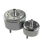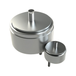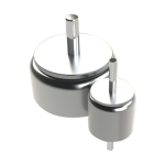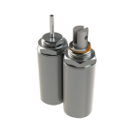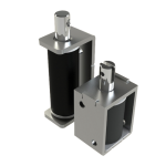
Visit our webpage for Shindengen DC Solenoids for a selection of standard models. Access to datasheets is provided within selection tables for each model.
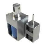
Technical Guides are also available for the total range of Shindengen DC Solenoid types & models: Rotary Solenoids, Push-Pull Solenoids, Small Push-Pull Solenoids, Tubular Solenoids, Open Frame Solenoids and Permanent Magnet Solenoids.
Ampere Turn
Ampere turn describes the electro-motive force that causes a solenoid to actuate. Ampere turn is the product of the applied current to the coil, multiplied by the number of turns of magnet wire, as shown in the following formula:
Voltage
Ampere Turns = Coil Resistance x Coil Number Turns
Energy output of a solenoid is proportional to the number of ampere turns. The larger the number of ampere turns, the larger the mechanical energy output. However, the ampere turns should not exceed 10% duty cycle, as above this level may cause coil thermal damage. Also, since all solenoids reach magnetic saturation at 10% duty cycle, increasing ampere turns will not increase energy output.
Arc Suppression
The solenoid coil is an inductive load which has a high inductance. As such, caution should be taken in the form of arc suppression when energizing and de-energizing the coil.
Duty Cycle
Duty cycle is the term used to define the heating factors of a solenoid to prevent thermal damage. Duty cycle is normally expressed as a percentage and is defined as the solenoid’s “on time” divided by the sum of the “on time” plus the “off time”:
On Time
Duty Cycle (%) = On Time + Off Time x 100
Duty cycle is important because a by-product of applying electrical power to the coil is heat. This excess heat can thermally damage the coil. Thus, the term “duty cycle” is used to assure that only the safe maximum amount of electrical energy is applied to the solenoid.
For example, if a solenoid is rated at 7 watts continuous duty, this means the solenoid coil can operate continuously (100% on time) with an input power level of 7 watts with no thermal damage. This continuous duty rating is arrived at by lab testing. If increased energy output is required, it can be accomplished by increasing the input power. However, this leads to increased temperature rise which can lead to permanent thermal damage in the coil. To prevent this, the solenoid must be operated in an “on” and “off” mode. Therefore, if the input power level is increased to 14 watts (double the continuous duty rating) the solenoid’s duty cycle must be dropped to 50% to prevent thermal damage. Additionally, the maximum “on” time needs to be considered.
Heat Sink
In order to reduce coil heating and to enable a larger number of ampere turns to be employed, a heat sink is attached to a rotary solenoid. Without a heat sink, a lower voltage than specified on the coil data charts or a lower duty cycle must be used to avoid thermal damage to the coil.
Coil data for rotary solenoids, push-pull solenoids, and tubular solenoids are also measured and tested with a standard heat sink attached. Coil data for small push-pull solenoids, self-holding solenoids, open frame solenoids and proportional/on-off solenoids is shown without use of a heat sink.
Maximum “On” Time
When a solenoid is actuated, current is applied to the coil. A by-product of this is temperature rise in the coil. When a solenoid is energized continuously, heating of the coil increases until a saturation level is reached which is equal to the ambient heat radiation. When a solenoid is operated in an intermittent (on-off) manner, the “on” time becomes critical if higher voltages (currents) are applied to the coil. These higher currents cause higher coil temperatures which can exceed the cooling capacity of the solenoid through ambient radiation. This heat rise can thermally destroy the solenoid’s coil. To avoid such a catastrophic failure, there is a maximum “on” time, which is the longest time the solenoid can be energized without thermal damage. The maximum “on” time has been determined for each duty cycle, and is shown in the coil data.
Pick and Hold Circuit
A pick and hold circuit is used when a large energy output from the solenoid is required, but the space is limited. A high voltage is applied to a coil during energizing (pick) and then applies a voltage to the coil to reduce potential coil heating problems (hold). The most frequently used method is a simple timing circuit that applies a high voltage signal for approximately 50 msec. and then drops off to a holding voltage. Dual coil designs can also be used; whereby one coil is used for “pick” and the other for “hold”.
Power Supply
All Shindengen standard solenoids are DC types. If the power supply available is AC, then a rectifier is required to convert AC to DC. The rectifier should be a full wave rectified type.
Response Time
The response time for solenoids is the duration from when voltage is applied to the coil until a given stroke has been achieved. The data in this catalog uses a coil temperature of 20°C as a reference point, without any load. Response time will become longer when a load is applied to the armature.
Safety Factor
To reduce potential problems due to energy loss through temperature rise in the coil and voltage fluctuations, a safety factor of 1.5 is recommended (required output x 1.5). When using open frame solenoids and self-holding solenoids, the safety factor should be 1.3. It is possible to use a smaller safety factor, but precise application testing should be performed under all possible conditions.
Temperature Effects on Performance
Coil and performance data shown in this catalog are measured at an ambient temperature of 20°C. When a voltage is applied to a coil, the coil temperature rises. This temperature increase causes an increase in the coil resistance. As a result. the energy output will decrease. The relationship between the coil temperature and the coil resistance are shown in the following table.
| Coil temp. (°C) | Resistance coefficient | Ampere-Turn ratio |
| -40 | 0.764 | 1.309 |
| -20 | 0.843 | 1.186 |
| 0 | 0.921 | 1.086 |
| 20 | 1 | 1 |
| 40 | 1.079 | 0.927 |
| 60 | 1.157 | 0.864 |
| 80 | 1.236 | 0.809 |
| 100 | 1.314 | 0.761 |
| 120 | 1.393 | 0.718 |
To select the appropriate solenoid, it is best to consider the final temperature of the solenoid to be used in your application. To determine the value of force or torque after the coil temperature increase, the ampere turns must be calculated from ambient temperature according to the following formula:
R2-R1
t = R1 x (234.5 + t1) + t1 – t2
A relationship exists between duty cycle and voltage. In the table below the relationship between ampere turn, power (watts), and voltage is represented. For example, the voltage at 25% duty cycle is twice the voltage at 100% duty cycle.

The voltage of a solenoid at a duty cycle not shown in the coil data, is determined by the following formula:

When the solenoid is used in an environment of high temperature and high humidity, and the case is grounded, the coil may corrode and fail under electrolytic action. To eliminate this potential problem, the following precautions should be observed:
Tables are provided for each size of push-pull solenoids, tubular solenoids, open frame solenoids, and self-holding solenoids, which show stroke vs. force curves at four duty cycles (100%, 50%, 25%, and 10%).
For rotary solenoids, the table represents duty cycle vs. torque curves for each rotation angle. Decide the size of the solenoid needed in your application, then move to the page for that size, and review details for the solenoid.
| 1N (Newton) | =0.102 (kgf)=102 (gf) |
| 1kgf | =9.807 (N) |
| 1Nm | =10.197 (kgf cm) |
| 1MPa | =10.197 (kgf/cm2) |
| 1kgf/cm2 | =0.098 (MPa) |
| 1N (Newton) | =0.225 (lbs) |
| 1Nm | =8.85 (lb • in) |
| 1MPa | =145PS1 |

Our Sales Team is available to answer any questions that you may have. Contact them today to learn more!