
Visit our webpage for Shindengen Permanent Magnet DC Solenoids to view all available models and for access to datasheets.
Permanent magnet solenoids (also known as magnetic-latching or self-holding solenoids) are a product line of linear open frame solenoids that incorporate the advantages of a high performance permanent magnet. The principle of operation is similar to all linear solenoids. When the coil is energized the plunger moves toward the pole piece. The advantage of the permanent magnet solenoid is that once energized and plunger movement has occurred, the plunger will remain in the energized position without any further electrical power input.
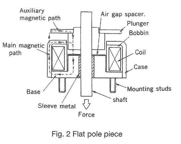
The “holding” feature is achieved by using the permanent magnet to create a magnetic latching field that maintains the plunger in the closed or energized position. There are two types of permanent magnet solenoid configurations; a one-direction holding design and a two-direction holding design. The one-direction design uses a permanent magnet to hold the solenoid in the energized position (see Fig 1). The two-direction design uses a permanent magnet to hold the enclosed plunger in two different positions at both ends of the stroke. The two-direction design includes two separate coils and pole pieces (see Fig 2).
Permanent magnet solenoids can be used in both short and long stroke applications. As such, the pole piece designs are both conical and flat depending upon the performance requirements. To improve efficiency the solenoid stroke should be minimized in the application.
A. Temperature
Coil data (see datasheet) for the permanent magnet solenoid shows the values at ambient temperature 20°C and a duty cycle of 25% (SH2LC0524 is duty cycle 10%). The solenoid coil can operate at temperatures up to 105°C. Most applications using permanent magnet solenoids are intermittent applications (the permanent magnet is used for holding). Please note the maximum on time to prevent potential thermal damage.
B. Operation
The permanent magnet solenoid is different than traditional solenoids in that electrical polarity is important to obtain proper operation. The lead wires from the coil are color coded and must be wired to the appropriate electrical connections (plus and minus terminals). With current flowing in one direction (when energizing the solenoid) the coil’s magnetic field and the permanent magnet field are additive. To release the solenoid from the “hold” position the coil field has to cancel the permanent magnet field, thus current has to flow in the opposite direction to the pull-in current flow.
C. Return Spring
In a one-direction design it is advantageous to use a return spring to prevent inadvertent plunger “pull-in” that could be caused by the magnetic field from the permanent magnet.
D. Plunger & Shaft Modification
It is not recommended that the user modify the plunger or shaft, as the shafts are manufactured and plated at the factory. Custom configurations can be considered by our factory.
E. Handling
The permanent magnet solenoid uses a permanent magnet that will attract metal particles and care must be taken to prevent these particles from becoming “attached” to the solenoid.
E. Solenoid Installation
The permanent magnetic solenoid uses tapped holes for mounting in the frame. Caution needs to be observed that the mounting screws used to attach these solenoids are the correct length so as not to damage the coil.
| Insulation class: | Class E (120°C), Lead wire class A (105°C) |
| Dielectric strength: | AC 1000V 50/60 Hz 1 min. (at normal temp. and normal humidity) |
| Insulation resistance: | More than 100 Mohm at DC 500V megger (at normal temp. and normal humidity) |
| Expected life: | 200,000 cycles |
Note: Solenoid cycle life is very dependent upon side load, frequency of use and environmental conditions. Cycle life tests should be performed by the user.
Before selecting a Permanent Magnet solenoid, the following information must be determined:
A. Attraction Force & Holding Force
The actual force required for both “pull-in” and “holding” in the application should be increased using a safety factor multiplier of 1.5 to arrive at the force value that should be used in your specification.
B. Duty Cycle
Most applications using permanent magnet solenoids are intermittent applications (the permanent magnet is used for holding), the duty cycle for each solenoid appears in the datasheet for each model. Please note the maximum on time to prevent potential thermal damage.
On Time
Duty Cycle (%) = On Time + Off Time x 100
C. Stroke
The stroke for a one-direction permanent magnet solenoid is determined by application requirements. For a two-direction permanent magnet solenoid the stroke is determined by the solenoid selected.
D. Operating Voltage
Operating DC voltage is determined by the application and voltage available.
Once solenoid specifications are determined the correct size solenoid can be selected for the application using the force-stroke characteristic tables and graphs located at the end of this guide. Coil data is available in the datasheet for different sizes of magnet wire.
Note: In a one-direction permanent magnet solenoid, to “release” the permanent magnet field so the plunger can return to the de-energized position the appropriate level of reverse current must be applied to the coil. The data for this “release” current is shown in the coil data provided in the datasheet for each solenoid size.
To determine the force output of the solenoid after temperature rise, please use the amp-turn force graphs located at the end of this guide, after calculating the amp-turns.
Use the datasheet for each model to select the appropriate part number.
Example of a complete part number:
| SH1LC0524-06 | SH2LC0730-12V |
| One-direction, conical, 6V coil | Two-direction, conical, 12V coil |
For Permanent Magnet solenoids without modifications the following part number system is used on product labels.
Example part number: SH1LC0524-06 9405
| SH1LC0524-06 | 9405 |
| Part Number | Date Code (year and week) |
Note: A custom solenoid (any modification to a standard design) requires the assignment of a special part number which will identify the custom model and date code.
Use the links below to access performance charts for Small Push-Pull Solenoids.
Our Sales Team is available to answer any questions that you may have. Contact them today to learn more!