
Visit our webpage for Shindengen Push-Pull DC Solenoids to view all available models and for access to datasheets.
The rotary solenoid’s design starts from a standard flat face push-pull solenoid. The rotary solenoid then incorporates the mechanical design principle of an inclined plane to convert linear motion to rotary motion. There are three uniform inclined planes (spiral grooves) that are stamped into both the case and the armature, called “ball races”. These provide both a means of converting linear motion to rotary motion and a secondary bearing system to support this rotary motion. (See Fig.1)
Features:
The output shaft is attached at either end of the solenoid. Thus, attaching the shaft on the base side actuates as a push solenoid. Attaching the shaft on the armature side actuates the solenoid in the pull mode.
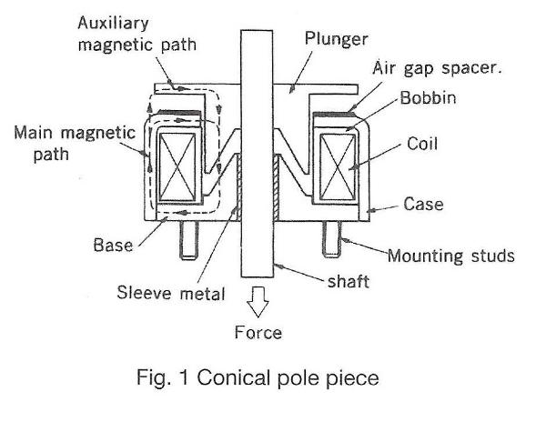
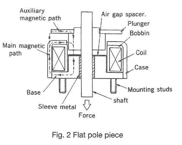
The push-pull solenoid is available with 2 standard pole piece configurations. The conical pole (Fig. 1) is meant for medium strokes (3-8mm). The flat pole piece (Fig. 2) is designed for short strokes (0-3mm), and where high holding force is required. Force-stroke curves for each size and configuration are shown in the catalog. For the best performance and efficiency, the stroke should be kept to a minimum.
A. Temperature
The coil data of push-pull solenoids shows the values at ambient temperature 20°C and with a standard heat sink. If a solenoid is used at a rating shown in the coil data, it is designed so that the coil temperature rises and reaches equilibrium at approximately 85°C. In applications where the ambient temperature is higher than 20°C or the heat sink is smaller than indicated in the catalog, possible thermal damage can occur. Temperature rise tests should be performed by the customer to assure that the coil does not reach 120°C. Coils can be constructed to operate at temperatures higher than 120°C without thermal damage. Please consult the factory for details.
B. Air Gap Spacer
The push-pull solenoid uses an air gap spacer between the armature and the case. This spacer is installed to prevent the armature and base from coming into mechanical contact with each other, which would cause residual magnetism.
C. Return Spring
The push-pull solenoid does not include a return spring. Therefore, the application must include a return spring.
D. Shaft Modification
It is not recommended that the customer modify the shaft, as the shafts are fabricated before assembly. Any special configuration can be supplied. Please consult the factory for details.
E. Solenoid Installation
The size 191C and 191F use tapped holes for mounting in the base. Caution needs to be observed that the mounting screws used to attach these solenoids are the correct length so as not to damage the coil.
| Insulation class: | Class E (120°C), Lead wire class A (105°C) |
| Dielectric strength: | AC 1000V 50/60 Hz 1 min. (at normal temp. and normal humidity) |
| Insulation resistance: | More than 100 Mohm at DC 500V megger (at normal temp. and normal humidity) |
| Expected life: | Standard life: 2 million cycles Extended life: 10 million cycles |
Note: Solenoid cycle life is very depended upon side load, frequency of use and environmental conditions. Cycle life tests should be performed by the user.
Before selecting a push-pull solenoid, the following information must be determined:
A. Force
The actual force required in the application should be increased using a safety factor multiplier of 1.5 to arrive at the force value that should be used in your specification.
B. Duty Cycle
Use the following formula to calculate duty cycle. Also note the maximum on time.
On Time
Duty Cycle (%) = On Time + Off Time x 100
C. Stroke
Stroke is determined by application requirements.
D. Operating Voltage
Operating DC voltage is determined by the application and voltage available.
After determining the specifications listed above, the correct solenoid for the application can be selected using the torque characteristics tables. Coil data is also provided in tables that use American Wire Gauge (AWG) for magnet wire. If the exact operating voltage is not in the coil data table use the nearest voltage shown in the table.
Note: When the operating voltage falls between 2 coil sizes, always use the higher AWG numbered coil to prevent potential thermal damage. To determine the torque output of the solenoid after temperature rise, please use the amp-turn gross torque tables located at the end of this technical guide after calculating the amp-turns.
When ordering a push-pull solenoid, the correct part number needs to be determined, from the following combination of characteristics (1-5):
Example of a complete part number:
| 1 | 2 | 3 | 4 | 5 |
| F | 341 | C | 30 | P |
The part number above distinguishes a Push-Pull solenoid with [1] SAE threads; [2] size 341; [3] with a conical plunger; [4] with 30 AWG coil wire; [5] standard life bearings.
For push-pull solenoids (no modifications) the solenoid label will include the part number and date code. The date code identifies the year and week of manufacture.
Example part number: F 341 C 30 P 9401
| F | 341 | C | 30 | P | 9401 |
| SAE Thread | Solenoid Size | Conical Plunger | Coil Wire AWG | Push-Pull & Bearing Life | Date Code (year and week) |
Note: A custom solenoid (any modification to a standard design) requires the assignment of a special part number which will identify the custom model and date code.
Use the links below to access performance charts for Rotary DC Solenoids.
Our Sales Team is available to answer any questions that you may have. Contact them today to learn more!