
Visit our webpage for Shindengen Tubular DC Solenoids to view all available models and for access to datasheets.
Tubular solenoids are designed and manufactured to obtain the maximum force output with the minimum of weight and size. Features include a large force output in a small size, minimum flux leakage by design, and a low level of operational noise. The structure consists of a slender cylinder as shown in Fig. 1 and 2. The outside case is a high permeable steel to improve efficiency. Both pull and push type configurations are available as standard models.
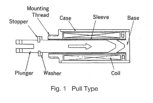
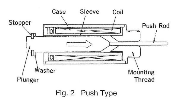
The tubular solenoid is designed for longer strokes than the conical push-pull type solenoid. As such, the pole piece designs are conical to maximize performance over longer strokes. To improve efficiency, the solenoid stroke should be minimized in the application.
A. Temperature
Coil data for the tubular solenoids shows the values at ambient temperature of 20°C and with a standard heat sink. If a solenoid is used at the ratings shown in the coil data, it is designed so that the coil temperature rises and reaches equilibrium at approximately 85°C. In applications where the ambient temperature is higher than 20°C or the heat sink is smaller than indicated in the datasheet, possible thermal damage can occur. Temperature rise tests should be performed by the user to assure the coil does not reach 120°C. Coils can be constructed by special request to operate at temperatures higher than 120″C without thermal damage.
B. Air Gap Spacer
The tubular solenoid has an air gap spacer installed between the plunger stopper and the case. This spacer is installed to prevent the plunger and base from mechanical contact with each other, which would cause residual magnetism.
C. Return Spring
The tubular solenoid does not include a return spring as a standard option. Therefore, the application must include a return spring or a custom modification may be requested to include it.
D. Plunger & Shaft Modification
It is not recommended that the user modify the plunger or shaft, as the shafts are manufactured and plated at the factory. Requests for custom configurations will be considered by the factory.
| Insulation class: | Class E (120°C), Lead wire class A (105°C) |
| Dielectric strength: | AC 1000V 50/60 Hz 1 min. (at normal temp. and normal humidity) |
| Insulation resistance: | More than 100 Mohm at DC 500V megger (at normal temp. and normal humidity) |
| Expected life: | Standard life: 2 million cycles Extended life: 5 million cycles Long life: 10 million cycles |
Note: Solenoid cycle life is very dependent upon side load, frequency of use and environmental conditions. Cycle life tests should be performed by the user.
Before selecting a tubular solenoid, the following information must be determined:
A. Force
The actual force required in the application should be increased using a safety factor multiplier of 1.5 to arrive at the force value that should be used in your specification.
B. Duty Cycle
Use the following formula to calculate duty cycle. Also note the maximum on time.
On Time
Duty Cycle (%) = On Time + Off Time x 100
C. Stroke
Stroke is determined by application requirements.
D. Operating Voltage
Operating DC voltage is determined by the application and voltage available.
After determining these specifications, the correct size solenoid for the application can be selected using the force-stroke characteristic tables and graphs. The coil data is also shown for different sizes of magnet wire. If the exact operating voltage is not in the coil data table, use the nearest voltage shown in the datasheet table.
NOTE: When the operating voltage falls between 2 coil sizes, always use the higher AWG numbered coil to prevent potential thermal damage. To determine the force output of the solenoid after temperature rise, please use the amp-turn force graphs located at the end of this guide after calculating the amp-turns.
When ordering a tubular solenoid, the correct part number needs to be determined, from the following combination of characteristics (1-5):
Example of a complete part number:
| 1 | 2 | 3 | 4 |
| F | 130 | 35 | LL |
The part number above distinguishes a Tubular solenoid with [1] SAE threads; [2] size 130; [3] with 35 AWG wire; [4] long-life (coatings on plunger) bearings.
For Tubular solenoids (no modifications) the solenoid label will include the part number and date code. The date code identifies the year and week of manufacture.
Example part number: F 130 35 LL 9401
| F | 130 | 35 | LL | 9401 |
| SAE Thread |
Solenoid Size |
Coil Wire AWG |
Tubular Pull & Bearing Life |
Date Code (year and week) |
Note: A custom solenoid (any modification to a standard design) requires the assignment of a special part number which will identify the custom model and date code.
Use the links below to access performance charts for Small Push-Pull Solenoids.
Our Sales Team is available to answer any questions that you may have. Contact them today to learn more!