

The Bicron Solenoid part numbering system is intended to specify the solenoid that will best meet the requirements of your application. You can create the part number starting with the solenoid model located on our solenoid product pages, then add specific features outlined below.
If your application requires a modified standard or custom model, please visit our webpage for Bicron Custom DC Solenoids.
Force: Take the force required in the application and multiply it by a safety factor of 1.5.
Stroke: This is the distance that the solenoid plunger will pull or push your load.
Duty Cycle: This is determined by applying the maximum time the solenoid will be on and the minimum time the solenoid will be off tot he formula below under Glossary of Terms.
Power: This is the toal amount of power to be made available for operation of the solenoid.

Linear solenoids are electromechanical devices which convert electrical energy into a linear mechanical motion used to move an external load a specified distance. Current flow through the solenoid coil winding creates a magnetic field which produces an attraction between a movable plunger and a fixed stop. When electrical power is applied, the solenoid’s plunger and its external load accelerates and moves toward the solenoid’s stop until an impact occurs. The plunger rides inside the core of the coil assembly. The core may be either a plastic bobbin or a non-magnetic metallic guide. Removal of power from the solenoid eliminates the current flow through the coil. The plunger, with its external load, returns to the rest position, aided by a return spring, gravity, or the load itself, which could also be spring loaded. In some cases, when the solenoid is energized and in the seated position, the only load might be that of the plunger plus the opposing force of the compressed spring.
The effects of residual magnetism (the remaining magnetic force after the solenoid has been de-energized) must be kept to a minimum by the proper selection of high quality, high permeability, magnetic iron. Solenoid design criteria must allow only a negligible amount of residual magnetism.
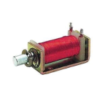
All linear solenoids are pull-type devices in the sense that the plunger assembly (along with its external load) is pulled in and moves toward the stop when the solenoid is energized. If, however, the plunger is adapted to include a push rod mounted to the inboard end of the plunger and extended through a hole in the stop, when it is pulled in the push rod would extend further back through the stop and could be used to push an external load a specified distance. Solenoids, therefore, can be provided as either Pull Type or Push Type (see Figs 4, 5 and 6).
The magnetic circuit of a solenoid is the channeling of the magnetic field’s flux lines through a metallic medium [iron], as well as air. The pattern of the radiated flux lines is toroidal. The flux lines radiate around the outside of the coil and concentrate in the core of the coil assembly in which the plunger rides. The magnetic efficiency of the solenoid is determined by the length of the flux path, air gaps in the magnetic circuit, or the magnetic permeability of the solenoid’s construction.
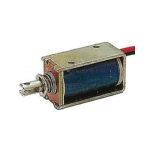
Typically, fully enclosed tubular solenoids are more magnetically efficient than open frame solenoids. This is because the path of the flux lines around the outside of the magnetic coil assembly is through a metal housing, rather than open air, as is the case with a C-frame or D-frame solenoid. The magnetic reluctance of a magnetic circuit is greatly reduced when the flux lines pass through materials of increased permeability- iron for example, versus free air. A D-frame solenoid has a partially enclosed magnetic circuit because the frame surrounds the coil assembly on two sides, but the tubular solenoid is still more efficient because its magnetic circuit is completely surrounded by a metallic housing (see Figs 1,2 and 3).
All solenoids have a working, or variable, air gap between the plunger and the stop, as well as a fixed air gap between the outside diameter of the plunger and either its frame, or, in the case of a tubular solenoid, its mounting bushing. To complete the magnetic circuit, the flux lines flow through either air, or a metallic frame, or a tubular housing around the coil assembly through the stop, the plunger, the frame or the mounting bushing of a tubular solenoid, and return to their point of origination.
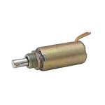
Open frame solenoids are referred to as C-frame and D-frame [or Box frame], depending upon the edge view of their metallic frame. Open frame solenoids are typically secured by mounting screws through a panel in the application and threaded into the solenoid’s frame. Tubular solenoids typically have a mounting bushing where either the plunger or the push rod exits the assembly, which is inserted through a hole in a panel in the application, and secured by a lock washer and nut.
Magnetic efficiency has a price in that tubular solenoids (Fig. 3) are usually more expensive than equally rated open frame solenoids. However, it is conceivable that a smaller tubular solenoid could perform as well or better than a larger open frame solenoid depending on the application. This is due to the improved magnetic efficiency of the tubular design. A C-frame (Fig. 1) solenoid, with its typical one-piece frame, is usually less expensive than a D-frame (Fig. 2) solenoid, which has a two-piece frame. The cost difference is mainly due to the elimination of one component, providing a reduction in material and assembly cost.
The best performance and cost effectiveness of a solenoid for a specific application depends on understanding key solenoid selection criteria:
Minimum force required at specific maximum stroke:
The performance of a solenoid is typically described by either a force/stroke graph or tabulated charts. Typically, the performance is shown for each solenoid model, and for each of its standard duty cycles.
The performance of a solenoid is greatly influenced by its physical size, the wattage applied, duty cycle, ambient temperature, its coil temperature (determined by the heat rise], the coil’s ampere turns (NI = current x coil turns), solenoid orientation, cross sectional area of the plunger and, finally, the coil winding and the plunger and stop geometry.
Large solenoids can outperform smaller solenoids at a given stroke and with the same coil current because their coil assemblies can accommodate more turns of magnet wire, resulting in a greater NI. In addition, one must be concerned about the variations in applied nominal voltage, sliding friction caused by side loading of the plunger assembly, and the effects of a return spring which creates an opposing force to the direction of plunger motion.
The slope of a force/stroke curve can be changed by modifying the geometry, or cone angles, of the internal end of the plunger and its mating stop. A 45° to 600 conical configuration is very common in the industry for standard solenoids. The effect of using various cone angles is shown in Fig.7. The graph applies to DC solenoids only. Another popular standard solenoid cone angle is a flat face which achieves the greatest holding force due to the flux lines and the force vector traveling in a straight line, parallel to the axis of the plunger and its stop. A stepped conical configuration is also shown.
In Figure 7, note the greater the holding force of a given plunger and stop geometry, the lesser the pulling or pushing force at an extended stroke position. The minimum pull or push force generated is at the extended stroke position, or at the point where the plunger assembly begins its travel toward the stop. As the plunger approaches the stop position, the pulling or pushing force developed increases dramatically, and the slope of the force/stroke curve rises sharply. The use of a stepped conical configuration, which is a combination of a flat face at the outside edges and a cone in the center, results in a stroke with a more constant force throughout its range.
Force and stroke data is usually measured factoring in the mass of the plunger and the opposing force of gravity. The solenoid is mounted in the vertical position with gravity opposing the direction of the plunger motion. External load lifting capacities are determined at pre-selected stroke positions. The data is usually taken at an ambient temperature of 20°C with a coil assembly that has not reached thermal equilibrium. Accordingly, a margin of safety must be included when specifying a solenoid, to allow for heat rise as well as other influencing variables in the actual application. We normally suggest a safety factor of 1.5. In the case of open frame magnetic latching type solenoids, operated on a pulse duty cycle, the required safety factor would be minimal since the self-heating of the coil assembly would be negligible.
DC power is the preferred solenoid power source because the performance of the solenoid will be more predictable, particularly if a regulated power supply is used. Voltage variations cause variations in applied wattage which result in variations in a solenoid’s force performance. In addition, a solenoid operated with DC power is much quieter than a solenoid operated with an AC input. At a frequency of 60Hz, a solenoid operated with an AC input would very audibly buzz when actuated. It would be preferable to rectify the AC input with a full-wave diode bridge and operate the solenoid with the resulting pulsating DC input. The RMS value of the pulsating DC could be pre-determined to optimize the performance of the solenoid and to match the coil characteristics to the input signal.
The characteristics of the solenoid’s coil winding are critical to its optimum performance. Solenoid designers attempt to maximize the “NI” of the coil (the coil current multiplied by the number of coil turns) to maximize the strength of the generated magnetic flux field. Design limitations include the physical space available in the bobbin coil window for the magnet wire, current limitations imposed by the application requirements, the temperature rating of the insulating materials (magnet wire insulation, bobbin material, insulation tapes and/or other non-metallic materials), and magnetic saturation points.
An intermittent duty cycle is a very effective way to reduce the total wattage requirement and to maximize the performance of a solenoid, the more intermittent, the better. The longer time that power is applied to a solenoid, the hotter its coil will become. As the coil heats up, its electrical resistance increases. With a fixed voltage input and a higher coil resistance, the applied wattage decreases and a thermal equilibrium is achieved. However, the work capability of the solenoid decreases. Under continuous duty operation the coil does not have the opportunity to cool down because the input power is always on.
On the other hand, a smaller solenoid could be used in the same application if one were to apply extra power or wattage for a very short period of time and remove the power for an extended period. This is because the solenoid would be operating cooler, and the increased wattage applied equates to increased work performed. The amount of wattage that could be applied is limited by the total temperature rating of the solenoid’s insulation system, as well as the magnetic saturation point of the magnetic materials used in its design.
Bicron Electronics Company uses an insulation system rated for Class A operation, a system rated for 105°C total temperature. We also offer three standard duty cycles for our standard pull and push type open frame and tubular solenoids, as well as our magnetic latching solenoids, of 10%, 25% and 100%. Each standard duty cycle has a maximum on-time for the duration of the power pulse. The maximum on-times decrease in duration from infinity for a 100% or continuous duty cycle rating to just a very few seconds for a very small solenoid with a 10% duty cycle rating.
Duty cycle is defined as the ratio of the on-time (duration of the power pulse) to the total cycle time (the sum of the on-time and the off-time). It is expressed by the formula:
On Time
Duty Cycle (%) = On Time + Off Time x 100
Ambient temperature is the temperature of the environment that the solenoid will operate in. The maximum operating temperature of the solenoid is determined by the solenoid’s insulation class. The total coil temperature cannot exceed the insulation class temperature. If the insulation class of the solenoid is 105°C, the maximum allowable temperature rise would be 85°C, for example, above an ambient temperature of 20°C (20°C + 85°C = 105°C). Also, when a solenoid heats up, the coil resistance increases, causing the energy output to decrease. Therefore, to make a proper solenoid selection, one needs to consider the final temperature of the solenoid for force, as well as the insulation class specification.
A typical way to reduce solenoid cost is to reduce solenoid size, resulting in reduced iron and copper content (smaller frame, plunger and coil assembly). The amount of electrical power or wattage required to meet the mechanical work requirements greatly influences the size of a solenoid required for a specific application. The more work (force x stroke) that has to be accomplished, the more wattage required for conversion to linear motion and mechanical work. Minimizing the load at extended stroke, and minimizing the stroke or travel required, will greatly reduce the size of the solenoid needed for the application. One should try to keep the total stroke requirement to a minimum. Usually, “total stroke” consists of two components: pre-travel and working stroke. The plunger movement before the load is picked up is known as pre-travel. A higher starting force will be generated, with a greater pre-travel, due to the momentum created. The portion of the total stroke during which the external load is moved is known as the working stroke.
Life expectancy is determined by the demands of the application as well as the inherent design of the solenoid. The force that the solenoid generates should be matched to the application’s load requirements. A solenoid that is too powerful for the needs of the application can eventually fail mechanically due to the excessive hammering on the stop by its plunger assembly. Misalignment of the plunger assembly, and the resulting side loading, can also dramatically affect life expectancy. Excessive heating of the coil assembly, due to either high ambient temperatures and/or excessive coil self-heating, can seriously affect the performance and life expectancy of a solenoid. Excessive voltage applied to a solenoid (voltage exceeding the solenoid’s coil rating and/or voltage applied for an excessive period of time in the case of an intermittent duty cycle solenoid) could conceivably cause a coil burn-out. In addition, excessive mechanical shock or vibration can affect life expectancy. Also, environmental conditions, including corrosive environments, high humidity and very low ambient temperatures where ice would form, could cause solenoid failure.
The final determination of which specific solenoid is best for your application can be complex due to the number of mechanical, electrical, environmental, and thermal factors that need to be considered. The objective should be to select the smallest, most effective, efficient, and least expensive solenoid for use in your application. The amount of available space is also an important factor which affects the decision. This consideration is often left until last which presents the solenoid manufacturer with additional design problems. Also, it can impact cost if a special design, and/or a modified standard design, has to be recommended to meet the needs of the application.
The space availability, total operating temperatures, heat sinking and free air movement, orientation of the solenoid relative to gravity, and the mechanical linkage of the load to the plunger assembly can all influence the final solenoid size.
If possible, the solenoid should be mounted in the vertical position to minimize side loading and friction resulting from gravitational forces. Vertical mounting will improve both the performance and the life of the solenoid by minimizing the wear between the plunger’s outer surface, and the bobbin’s inner core surface.
Our Sales Team is available to answer any questions that you may have. Contact them today to learn more!